|

|
Are these normal signals for a ford ignition module?
|
|
|
| |
|
|
jkcobain
Novice
Dec 5, 2016, 11:08 AM
Post #1 of 14
(1472 views)
|
|
Are these normal signals for a ford ignition module?
|
Sign In
|
|
Hello everyone.
I'm rather new on car repairing, son I don't know whether the signals sent by the crank sensor to the ignition module, are correct.
The truck is a Ford Ranger 1996. The module is like this: http://easyautodiagnostics.com/images/articles-0-99/60/63/image_11.jpg
And the signals I got from the crank sensor are these:
http://i.imgur.com/LbLWtaJ.png
The problem is that the truck won't start, and the problem is that one of the coils is not generating spark (the one on the right side, if watching the motor from the front). I checked a lot of things, and everything looks fine (the coil does work, the ignition module does work), so now I'm only concerned about the crank sensor. Or do you have any suggestion to fix this problem?
Thank you a lot in advance!!
|
|
| |
|
|
kev2
Veteran

Dec 5, 2016, 11:31 AM
Post #2 of 14
(1460 views)
|
|
Re: Are these normal signals for a ford ignition module?
|
Sign In
|
|
which engine 4.0L?
What codes are showing?
there is no spark form coil ( coil pack) all plugs or just 1 or 2 terminals no spark?
At coil KOEO all 4 wires have 12v? yes or no?
|
|
| |
|
|
Hammer Time
Ultimate Carjunky
/ Moderator

Dec 5, 2016, 12:12 PM
Post #3 of 14
(1456 views)
|
|
Re: Are these normal signals for a ford ignition module?
|
Sign In
|
|
The first link is a restricted site so it won't let us in.
On the wave forms you have 2 channels. What is the other channel, cam sensor?
~~~~~~~~~~~~~~~~~~~~~~~~~~~~~~~~~~~~~~~~~~~~~~~~~~~~~~~~~~~~~~~~~~~~
We offer help in answering questions, clarifying things or giving advice but we are not a substitute for an on-site inspection by a professional.
|
|
| |
|
|
Discretesignals
Ultimate Carjunky
/ Moderator

Dec 5, 2016, 5:02 PM
Post #4 of 14
(1434 views)
|
|
Re: Are these normal signals for a ford ignition module?
|
Sign In
|
|
Looks like you have the 2.3L with dual coil packs. One coil is for the intake side of plugs and the other is for the exhaust side. If the intake side is working the engine should run.
The crank sensor and cam sensor is EDIS and both should be an analog sine wave. Where did you take the capture at? Is that at the ignition control module?
Since we volunteer our time and knowledge, we ask for you to please follow up when a problem is resolved.
|
|
| |
|
|
Discretesignals
Ultimate Carjunky
/ Moderator
Dec 6, 2016, 8:18 AM
Post #8 of 14
(1404 views)
|
|
Re: Are these normal signals for a ford ignition module?
|
Sign In
|
|
The crank sensor is a two wire variable reluctance sensor. It should produce a sine wave that changes in amplitude and frequency with engine speed. The engine computer receives the crank and cam sensor signal and then takes that information and sends a low amperage coil control signal to the ignition control module. The ignition control module then uses that signal to control the transistors that turn the coils on and off.
The input signals to the ignition control module are from the engine computer. They should be digital on and off. Can you capture the coil control signal from the module at the intake ignition coil? Back probe the tan/white and tan/orange on the primary coil. Be sure your scope is attenuated cause the voltage kickback spike can be pretty high. If you have an amp probe can you scope the primary coil amperage?
The primary waveform for each coil should look like this:
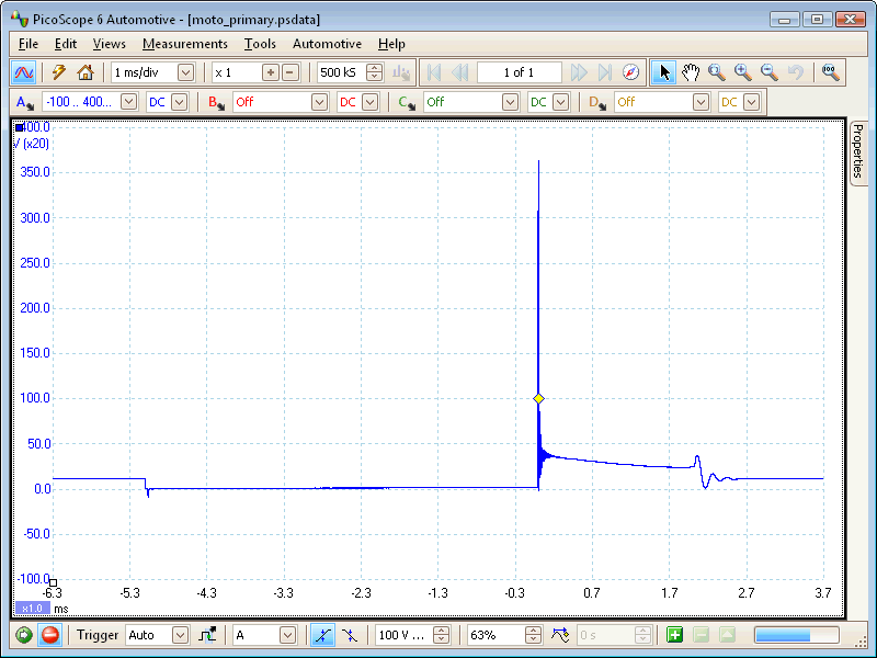
Since we volunteer our time and knowledge, we ask for you to please follow up when a problem is resolved.
(This post was edited by Discretesignals on Dec 6, 2016, 8:23 AM)
|
|
| |
|
|
Hammer Time
Ultimate Carjunky
/ Moderator
Dec 6, 2016, 10:12 AM
Post #9 of 14
(1384 views)
|
|
Re: Are these normal signals for a ford ignition module?
|
Sign In
|
|
I've had a couple of these that had one side of the ignition module burned out.
~~~~~~~~~~~~~~~~~~~~~~~~~~~~~~~~~~~~~~~~~~~~~~~~~~~~~~~~~~~~~~~~~~~~
We offer help in answering questions, clarifying things or giving advice but we are not a substitute for an on-site inspection by a professional.
|
|
| |
|
|
jkcobain
Novice
Dec 8, 2016, 9:58 AM
Post #10 of 14
(1353 views)
|
|
Re: Are these normal signals for a ford ignition module?
|
Sign In
|
|
The crank sensor is a two wire variable reluctance sensor. It should produce a sine wave that changes in amplitude and frequency with engine speed. The engine computer receives the crank and cam sensor signal and then takes that information and sends a low amperage coil control signal to the ignition control module. The ignition control module then uses that signal to control the transistors that turn the coils on and off.
The input signals to the ignition control module are from the engine computer. They should be digital on and off.
Ok! Is clear now, thank you!
Can you capture the coil control signal from the module at the intake ignition coil? Back probe the tan/white and tan/orange on the primary coil. Be sure your scope is attenuated cause the voltage kickback spike can be pretty high. If you have an amp probe can you scope the primary coil amperage?
I checked that signal, and I remember I saw something very similar to what you posted, unfortunately, I didn't save the capture, and since the car won't start, it is at the client's house. I will try to go there and get that capture, and hopefully you can help with that.
Also, I don't have an amp probe, so I won't be able to get that one :/
|
|
| |
|
|
Hammer Time
Ultimate Carjunky
/ Moderator
Dec 8, 2016, 10:14 AM
Post #12 of 14
(1346 views)
|
|
Re: Are these normal signals for a ford ignition module?
|
Sign In
|
|
What about the coils? Have you tried swapping them?
~~~~~~~~~~~~~~~~~~~~~~~~~~~~~~~~~~~~~~~~~~~~~~~~~~~~~~~~~~~~~~~~~~~~
We offer help in answering questions, clarifying things or giving advice but we are not a substitute for an on-site inspection by a professional.
|
|
| |
|
|
Discretesignals
Ultimate Carjunky
/ Moderator
Dec 10, 2016, 12:16 PM
Post #14 of 14
(1302 views)
|
|
Re: Are these normal signals for a ford ignition module?
|
Sign In
|
|
This might be really important information that I ran up on. It helps to understand how the system functions.
OPERATION - During engine cranking, the PCM will only fire the spark plugs on the right-hand side of the engine. When the engine has started, the PCM will start normal twin-plug operation.
So...the exhaust side will fire during cranking and once the PCM determines the engine starts it will allow control of the intake side coils to occur. If it doesn't start, you won't see any coil activity on the intake side. What I had stated about it not starting unless the intake coil is working was false.
Obviously, the crank sensor input is reaching the ignition module, the ignition module has power and ground, and the module is able to control the exhaust coil pack.
Does this have fuel pressure? Will it start up if you spray some starting fluid into the intake? Does the check engine light come on when you turn the ignition to on? Does the check engine light go out while the engine is cranking? These are important questions and your answers would give guidance.
I really sat down and look over the vehicle in SI. Are you sure this is a 1996? According to SI the ignition module was incorporated into the PCM when EEC V came along. 1996 OBD2 was mandatory on all American sold vehicles and the older EEC IV didn't support that. What is the history on this vehicle??
Since we volunteer our time and knowledge, we ask for you to please follow up when a problem is resolved.
(This post was edited by Discretesignals on Dec 10, 2016, 12:53 PM)
|
|
| |
|
| | |
|
