|

|
Bumperbozo
User
Sep 25, 2017, 3:53 PM
Post #1 of 13
(1638 views)
|
|
Haynes wiring diagram
|
Sign In
|
|
Guys, I'm trying to hook up an actron trigger remote starter switch to the 5sfe in my gen6 gt. I'm mostly making sense of it, but I don't want to burn something by running too much current by hooking it up to the wrong place. So there must be some resistance in the circuit. I don't know if that's in the starter solenoid and I can just hook it up to terminal 50 and the battery positive, or if it's elsewhere. Looking at this diagram I see a couple rectangular boxes, that are usually the symbols for resistors, but the markings I don't understand. For instance, does anyone know what EB1 is, just above the neutral start switch?
https://photos.app.goo.gl/uwnNpsGVY7Lqcz8N2
|
|
| |
|
|
Hammer Time
Ultimate Carjunky
/ Moderator

Sep 25, 2017, 3:55 PM
Post #2 of 13
(1634 views)
|
|
Re: Haynes wiring diagram
|
Sign In
|
|
What does a resister have to do with anything? You are looking for a power supply, right?
PS, you need to do a better job scanning that diagram. Can't read anything.
~~~~~~~~~~~~~~~~~~~~~~~~~~~~~~~~~~~~~~~~~~~~~~~~~~~~~~~~~~~~~~~~~~~~
We offer help in answering questions, clarifying things or giving advice but we are not a substitute for an on-site inspection by a professional.
(This post was edited by Hammer Time on Sep 25, 2017, 3:56 PM)
|
|
| |
|
|
Bumperbozo
User
Sep 25, 2017, 5:51 PM
Post #3 of 13
(1619 views)
|
|
Re: Haynes wiring diagram
|
Sign In
|
|
some resistance is the thing the prevents too much current from frying my trigger switch and possibly harming something else in the car. hooking it up to terminal C and battery positive, for instance, would probably melt it in my hand.
|
|
| |
|
|
Hammer Time
Ultimate Carjunky
/ Moderator
Sep 25, 2017, 5:56 PM
Post #4 of 13
(1617 views)
|
|
Re: Haynes wiring diagram
|
Sign In
|
|
I think you need to learn a little about electrical circuits before you tackle this.
The item you are powering IS the resistance in the circuit and the circuit will only carry as much current as your component consumes. The only thing you need to be concerned with is make sure the circuit you choose can handle the extra current being added by your component.
You first need to know how much current this component will consume.
Is this the thing you are trying to use?

~~~~~~~~~~~~~~~~~~~~~~~~~~~~~~~~~~~~~~~~~~~~~~~~~~~~~~~~~~~~~~~~~~~~
We offer help in answering questions, clarifying things or giving advice but we are not a substitute for an on-site inspection by a professional.
(This post was edited by Hammer Time on Sep 25, 2017, 6:03 PM)
|
|
| |
|
|
Bumperbozo
User
Sep 26, 2017, 3:16 PM
Post #5 of 13
(1575 views)
|
|
Re: Haynes wiring diagram
|
Sign In
|
|
yes, that's the switch I have.
I googled and found a legend from a manual to a similar model and it looks like the EB1 is a harness to harness connection. Can't find it, tho. Wish I could because the solenoid contact is hard to get to, and I was expecting to find just terminal 50 on the front of it, but it looks like there are two connectors there.
the bigger gray one has something like 15~40 embossed on it.
|
|
| |
|
|
Hammer Time
Ultimate Carjunky
/ Moderator
Sep 26, 2017, 3:43 PM
Post #6 of 13
(1571 views)
|
|
Re: Haynes wiring diagram
|
Sign In
|
|
I don't know what you are trying to do with this thing. All it is is a tool to assist with cranking the engine while you are taking a compression test or working on the engine.
It's a very simple hookup. One wire has to go on the trigger wire for the starter solenoid and the other just clips on the positive post of the battery. This is not something that gets installed permanently. It is a tool.
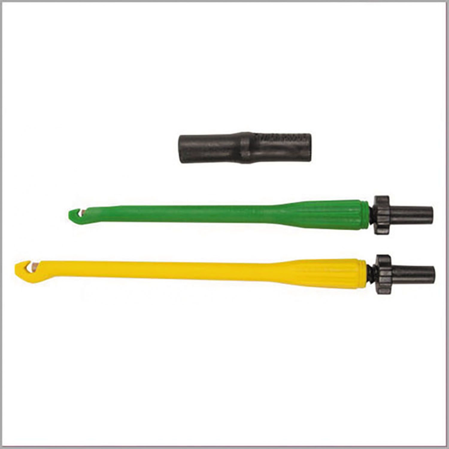
If you can't reach the connection at the starter, then just use something to tap into the wire further away from the starter like these.
~~~~~~~~~~~~~~~~~~~~~~~~~~~~~~~~~~~~~~~~~~~~~~~~~~~~~~~~~~~~~~~~~~~~
We offer help in answering questions, clarifying things or giving advice but we are not a substitute for an on-site inspection by a professional.
|
|
| |
|
|
Bumperbozo
User
Sep 26, 2017, 3:47 PM
Post #7 of 13
(1565 views)
|
|
Re: Haynes wiring diagram
|
Sign In
|
|
Cool, what are those? Yes, compression test.
|
|
| |
|
|
Hammer Time
Ultimate Carjunky
/ Moderator
Sep 26, 2017, 4:05 PM
Post #8 of 13
(1561 views)
|
|
Re: Haynes wiring diagram
|
Sign In
|
|
They are tools to tap into a wire.
~~~~~~~~~~~~~~~~~~~~~~~~~~~~~~~~~~~~~~~~~~~~~~~~~~~~~~~~~~~~~~~~~~~~
We offer help in answering questions, clarifying things or giving advice but we are not a substitute for an on-site inspection by a professional.
|
|
| |
|
|
Bumperbozo
User
Oct 4, 2017, 1:18 PM
Post #9 of 13
(1529 views)
|
|
Re: Haynes wiring diagram
|
Sign In
|
|
Cool, but isn't there another name for them that may be easier to Google?
|
|
| |
|
|
Hammer Time
Ultimate Carjunky
/ Moderator
Oct 4, 2017, 1:26 PM
Post #10 of 13
(1525 views)
|
|
Re: Haynes wiring diagram
|
Sign In
|
|
Wiring probes
~~~~~~~~~~~~~~~~~~~~~~~~~~~~~~~~~~~~~~~~~~~~~~~~~~~~~~~~~~~~~~~~~~~~
We offer help in answering questions, clarifying things or giving advice but we are not a substitute for an on-site inspection by a professional.
|
|
| |
|
|
Bumperbozo
User
Oct 4, 2017, 2:04 PM
Post #11 of 13
(1517 views)
|
|
Re: Haynes wiring diagram
|
Sign In
|
|
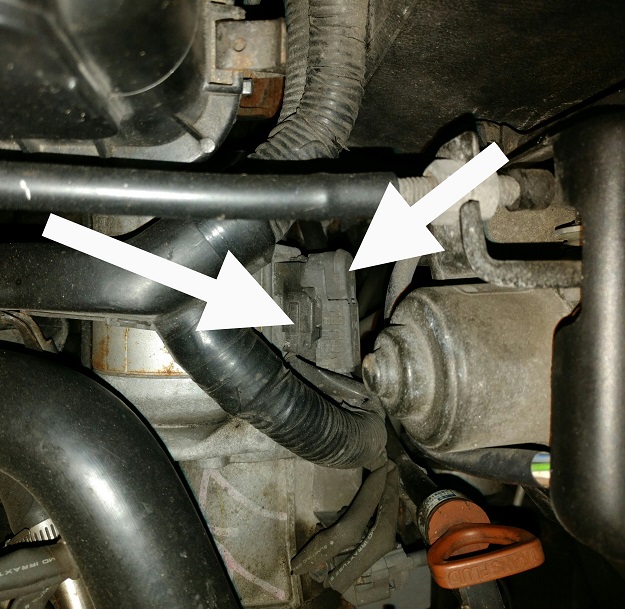
Awesome. Any idea which of the two arrows points to the start signal and which one is the motor current?
|
|
| |
|
|
Hammer Time
Ultimate Carjunky
/ Moderator
Oct 4, 2017, 2:09 PM
Post #12 of 13
(1515 views)
|
|
Re: Haynes wiring diagram
|
Sign In
|
|
I can't tell anything from your picture but the difference is very obvious. The power supply for the starter will be a battery cable size wire with constant power and the solenoid trigger that you are looking for will be a very small wire, only hot in start mode.
~~~~~~~~~~~~~~~~~~~~~~~~~~~~~~~~~~~~~~~~~~~~~~~~~~~~~~~~~~~~~~~~~~~~
We offer help in answering questions, clarifying things or giving advice but we are not a substitute for an on-site inspection by a professional.
|
|
| |
|
|
Bumperbozo
User
Oct 4, 2017, 2:18 PM
Post #13 of 13
(1511 views)
|
|
Re: Haynes wiring diagram
|
Sign In
|
|
Yeah, figured the smaller one was probably money, but I don't know that there isn't another wire behind the housing.
|
|
| |
|
